 Riku Färm
Anisotropy has now been a hot topic in the glass industry for the past couple of years. In fact, this is now the fifth anisotropy-related blog in Glastory in just four years. And apart from the articles, there have been two #AskGlaston videos dedicated to the issue.
Since discussions around anisotropy started heating up, a lot of development has taken place, especially in regard to new measurement equipment.
Even though measurement devices are nowadays able to provide a good amount of valuable information about anisotropy, we are still far away from being able to objectively state whether a particular anisotropy level in a given glass sheet is acceptable or not. In the coming years, we can expect to see significant developments on this front as well, as glass processors and different industry groups work together toward the common goal of defining one standard.
Nevertheless, using today’s online measuring devices gives you the possibility of ensuring you deliver consistent quality for your projects, whether there’s a standard or not.
Much of the discussion has revolved around anisotropy measurement. You might ask, why even measure something you can’t improve? The old adage, however, applies here very well: “What you don’t measure, you can’t improve!”
This blog aims to give you ideas on how to affect the anisotropy pattern and its intensity in your glass – with any kind of tempering machine. At this point, it’s up to you to decide which kind of pattern you think looks best.
Anisotropy is caused by stress differences created inside a glass sheet in the tempering process. In that sense, the principle of controlling anisotropy is very simple: reduce stress differences as much as you can. And even though it is not possible to completely avoid them when tempering, it is certainly possible to affect what kind of anisotropy pattern you are creating during your process. But keep in mind, reducing anisotropy is always asking for sacrifices somewhere else.
Below, you can find valuable tips for controlling anisotropy in the tempering process. The tips are related to the main tempering phases of heating and cooling.
Usually, a large portion of visible anisotropy pattern is created during the heating stage of the process. Every furnace model is a bit different based on the mechanical structure and the heating method it uses. Still, in normal production, there will always be temperature differences inside the glass – which lead to stress differences. The faster you heat the glass, the greater stress differences it will experience. That’s why to achieve more uniform heating, you need to slow down the process.
By lowering the furnace temperature and therefore increasing the heating time, your glass will heat up more evenly. This will also increase your cycle time. How much longer the cycle runs will depend on the heating technology capability of your furnace and how much you want to optimize heating.
Sacrifice: Capacity
Use as long oscillation length as possible and slow down the glass movement in the furnace to minimize stopping points. If possible, utilize alternating stopping points to avoid creating patterns on the glass due to cold areas.
If you’re trying to achieve a similar anisotropy pattern in all glasses, the most efficient way is to run only one glass sheet per load. When loading several glasses into the furnace at the same time, this will lead to differences in the patterns.
Look at the example below in Image 1, where two glasses have been tempered one after another in the same load. In this case, the first glass has a hot area in the middle, whereas the other one has a cold area in the same spot. This has happened because the first glass absorbed a lot of heat from the rollers in this particular location. As a result, the second glass went through much colder rollers in that zone.
Sacrifice: Capacity
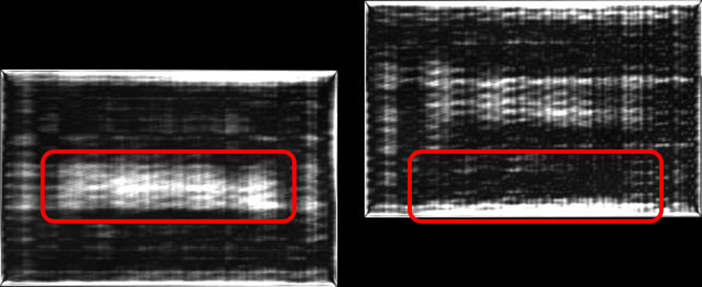
Leading glass Trailing glass
Usually, it’s safer to run glass a bit happy (with its corners up) to avoid leaving the glass corners in the furnace. However, this also means that the glass center will be hotter than the edges after heating. If you’re able to keep the glass flat in the furnace, the heating result will also be more even. To achieve this, you might need to decrease the production pace. However, there is a risk you end up with more defective glasses after the process.
Remember also to adjust the process slowly – step by step – to avoid damaging the furnace rollers.
Sacrifice: Capacity and possibly yield
Glass quenching issues are also clearly visible from the anisotropy pattern. Most commonly, you will be able to see kevlar marks and horizontal stripes in the pattern.
Optimizing anisotropy created in the chiller mainly comes down to optimizing only the first stopping point.
Often, you can find distinctive horizontal stripes in the glass. These marks are caused when the glass stops in the chiller during oscillation. If the glass temperature is too high, the stopping point will cause stress differences in the glass. So, what you are seeing as the result is actually caused by the rollers. Hence, the marks are horizontal.
These marks can be created with surprisingly low temperatures, even when the glass temperature is still under 400 °C.
Below in Image 2 are two examples. Both glass sheets were run with the same settings, except for the transfer speed. The first glass was run with a much slower transfer speed, which means that it had more time to cool down before the first stopping point. The second glass was run with a higher transfer speed and stopped with a higher temperature, leading to distinctive marks on the glass.
Lowering transfer speed doesn’t come without sacrifices. Especially with thinner glasses, edge lift can become a problem.
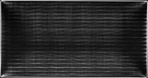 200 mm/s
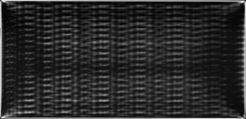 500 mm/s
Sacrifice: Capacity and possibly quality
The chiller doesn’t have the same kind of memory effect, but where you load the glass still has a huge impact on your anisotropy pattern. The reason for this is the same as explained in quenching tip #1 ‒ the glass that enters the chiller first will have a longer time to cool down before the first stopping point.
Therefore, you could run a full load with a slow transfer speed. Then, the first glass would look like the upper glass in Image 2, whereas the second glass would look like the bottom glass in that image.
This issue can be solved by running shorter loads or by having a long enough chiller so that all glasses have enough time to cool down before stopping.
If you’re going for a longer chiller, you need to consider a larger footprint, higher investment cost and higher energy consumption during the process. Alternatively, you could also consider adding a second chiller to your plant. However, this can be costly and requires some extra floor space.
Sacrifice: Capacity, investment cost, energy, floor space
There are also some other steps that can be taken to optimize anisotropy.
If you need to reduce kevlar marks, fully corded rollers can be used. This will help to create a more uniform pattern.
Note that this type of rollers works well primarily with thick glass. If you’re running thin glass, fully corded rollers will prevent air flow in the chiller, causing glass quality issues.
Sacrifice: Quality
If you’re a glass processor, remember that it’s always possible to affect the anisotropy pattern. It only takes adjusting a couple of key parameters or your glass loading method.
Still, to achieve optimized anisotropy, you must be willing to sacrifice something. This might be capacity, cost effectiveness due to higher investments, loss of glass quality or something else.
If anisotropy isn’t a crucial issue for your project, optimizing its pattern means wasting money. Yet being able to deliver glass with less disturbing anisotropy than average on the market might open up new, exciting business opportunities for you.
If you’re an architect, designer or end user of the glass, keep in mind that achieving a more uniform anisotropy pattern means a higher cost of producing such glass. Therefore, if minimizing anisotropy is crucial for your project, it’s also likely that the glass will be more expensive than normal. Therefore, make sure that your requirements for anisotropy are clearly agreed on in advance with your supplier.
The good thing is that state-of-the-art tools to help you agree on suitable anisotropy already exist on the market today. Advanced measurement equipment provides an efficient way to quantify the anisotropy level and even simulate images of the anisotropy pattern. So, why not take them into use?
Finally, before there are any universal evaluation methods, remember that it’s possible to have two glasses with very similar anisotropy values but very different anisotropy patterns. If two different patterned glasses are installed in the same building, they will more likely catch a viewer’s eye than if all glasses have a similar pattern.
Für den Glastory-Newsletter anmelden

Wir beantworten Ihre Fragen zur Glasverarbeitung. Teilen Sie uns Ihre Herausforderungen mit und wir versprechen, unser Bestes zu tun, um Ihnen zu helfen.
Comments are closed.